Lpg Piping System Design Calculations
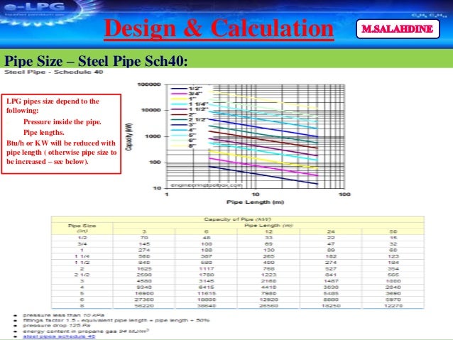
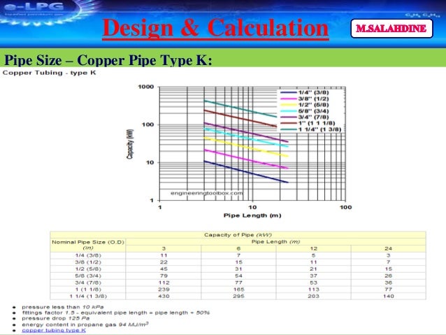
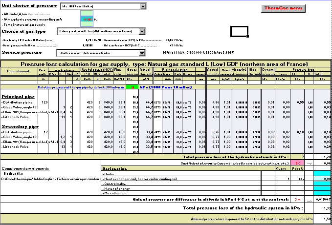
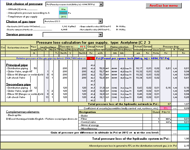
Lpg piping system design calculations. Of the size of the pipe and tubing the tank or the number of cylinders and the regulator will be based on the capac-ity of the system to be served. LPG Pipeline Design of a Hotel A Capsule Proposal. A design of gas 2 distribution system network in commercial gas piping system is going to be design and the pressure drop will be calculated according to Coxs and Poles rule.
The environmental application factors given in Table 1-2 are not to be confused with the Design Factor DF used in previous editions of the PPI Handbook and in older standards. Table Reprinted From Table 5421 NFPA 54 2002 ed. The design pressure would be at 1 psig in horizontal pipe flow and the natural gas NG was used as the main feed to the customer as a fuel.
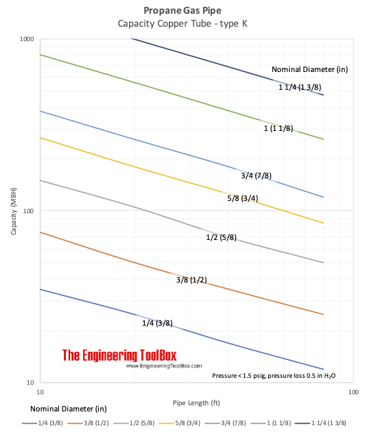
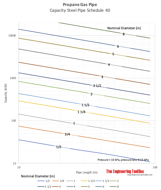
TABLE 3 GAS REQUIRED FOR COMMON APPLIANCES APPLIANCE APPROX. There are other methods available for sizing these systems by either a complex formulaic method. Gases and Compressed Air - Air LNG LPG and other common gas properties pipeline capacities sizing of relief valves.
You should enter not selected one. So for example the NFGC applies to the installation of all fuel gas piping systems and the equipment and appliances that are. The design method known as Design by Rule uses design pressure allo wable stress and a design formula compatible with t he geometry of the part to calculate the m inimum required thickness of.
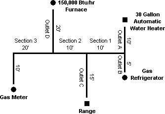
Both of these hydrocarbons are gasses under normal. The term LPG is most commonly used to refer to the common groupingmixture of two of the light hydrocarbon family Propane C 3 H 8 and Butane C 4 H 10. 2 Determine the length of pipe from the gas meter to the most remote outlet outlet A is 60 feet.
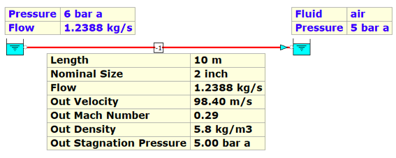
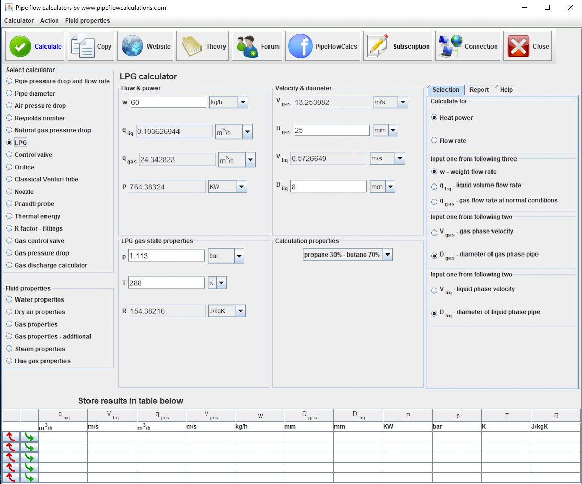
Gas Pipe Line Calculation Sizing For Steel Pipe Using CPC Pipe Sizing Table Natural Gas This handout will guide you thru the basic most common method for sizing a natural gas piping system for any residential or commercial application. - One cubic foot of LP gas 1000 BTU. Consider for example the simple system is shown below which consists of a single pipe with a nozzle on one end.
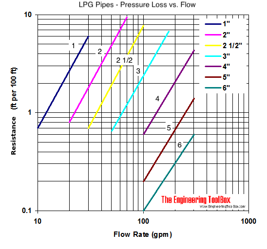
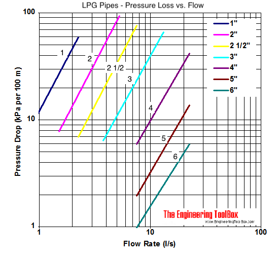
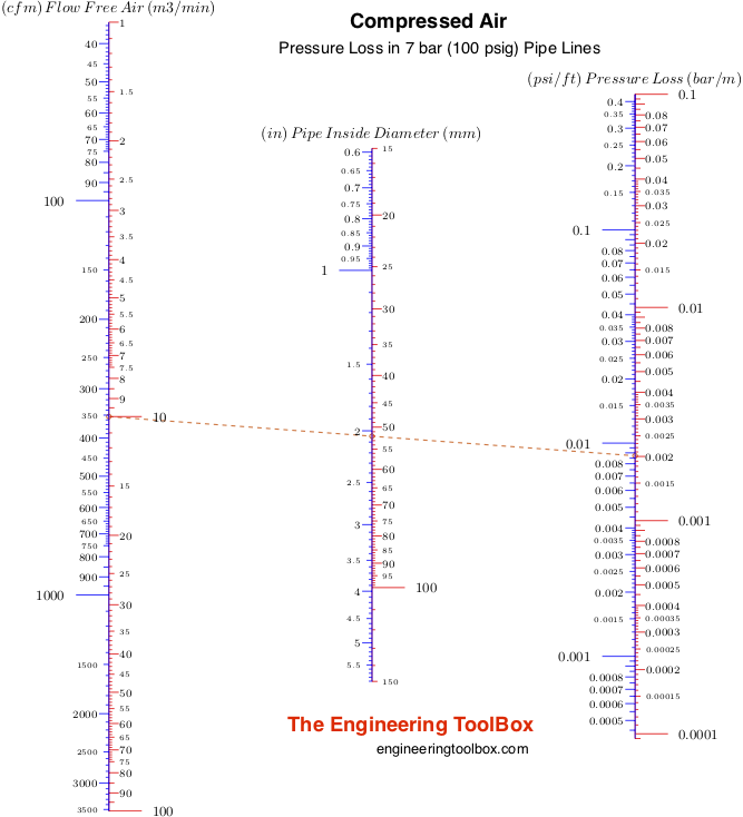
50 years experience with design of LPG piping systems Dimensioning and supply of com-plete LPG piping systems We only use internationally ac-knowledged suppliers of compo-nents. Fluid Flow and Pressure Loss - Pipe lines - fluid flow and pressure loss - water sewer steel pipes pvc pipes copper tubes and more.
TABLE 3 GAS REQUIRED FOR COMMON APPLIANCES APPLIANCE APPROX.
There are other methods available for sizing these systems by either a complex formulaic method. The pressure and temperature requirements and the chosen wall-thickness calculation formula dictate the resulting pipe wall thickness required for the piping or pipeline design. Consider for example the simple system is shown below which consists of a single pipe with a nozzle on one end. Gases and Compressed Air - Air LNG LPG and other common gas properties pipeline capacities sizing of relief valves. Gas Pipes - Approved Materials - Materials approved for gas pipes. Both of these hydrocarbons are gasses under normal. Table Reprinted From Table 5421 NFPA 54 2002 ed. 2 Determine the length of pipe from the gas meter to the most remote outlet outlet A is 60 feet. This network can be represented schematically by the diagram shown below Fig.
Fluid Flow and Pressure Loss - Pipe lines - fluid flow and pressure loss - water sewer steel pipes pvc pipes copper tubes and more. The environmental application factors given in Table 1-2 are not to be confused with the Design Factor DF used in previous editions of the PPI Handbook and in older standards. LPG is mainly used for cooking heating and auto fuels. The specification and grade of pipe and fitting materials selected for the design must be compatible with each other chemically eg carbon content so that the fittings can be welded to the pipe. The design pressure would be at 1 psig in horizontal pipe flow and the natural gas NG was used as the main feed to the customer as a fuel. The pressure and temperature requirements and the chosen wall-thickness calculation formula dictate the resulting pipe wall thickness required for the piping or pipeline design. Sec 1 10 Sec 2 10 Sec 3 30 60 3 Using the length in.
















Post a Comment for "Lpg Piping System Design Calculations"